
- Understand project configuration, templates, and cross reference formulas
- Create and edit line diagrams, associate symbols to components, draw multiple scheme wires
- Find and create relationships between manufacturers parts and circuit symbols
- Create and modify multi-wire styles, and customize wire numbering by style and/or equipotential
- Create user defined cable and cores
- Create and modify symbols, symbol properties, circuits, terminals and passing types
- Add origin-destination arrows to wires, replace and edit existing wire marks.
- Create and modify PLC marks, symbols, and configurations, automatically create PLC drawings
- Create 2D Cabinet layouts, utilizing cabinets, ducts, and rails. Optimize From-To wire cabling
- Check designs using design rule checks for conflicts with equipotential, fuse requirements, duplicates, and wire gauge
- Create Bill of Materials, list of cables, and drawing list reports
Lesson 1: Project Templates
- Starting SOLIDWORKS Electrical
- The User Interface
- What are Projects?
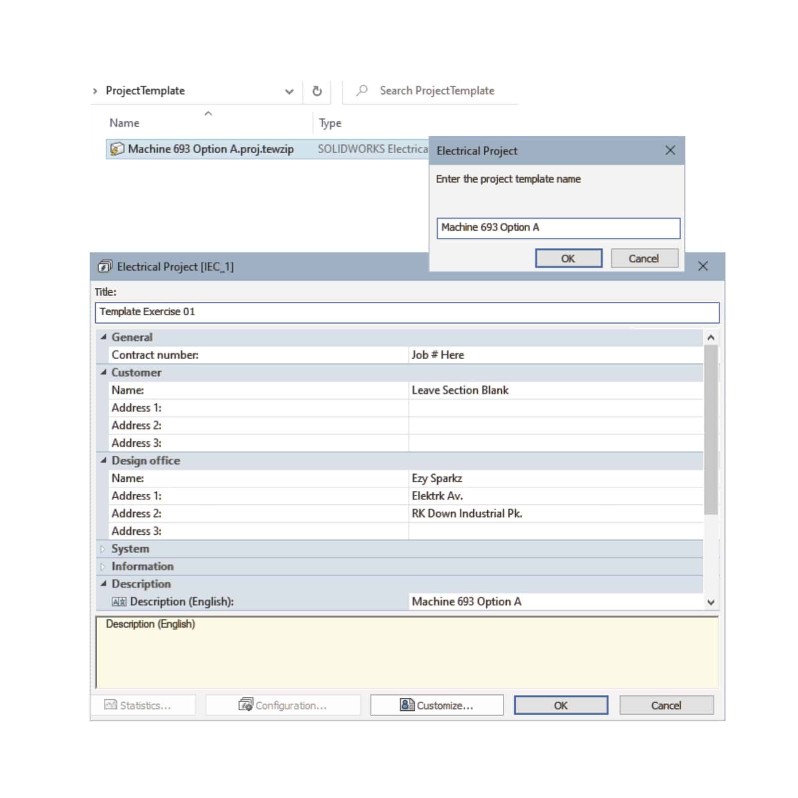
- Project Templates
- Project Configurations
- General
- Graphic
- Symbol
- Attribute
- Text
- Mark
- Title Blocks
- Libraries and Palettes
- How is a Project Structured?
- Book
- Folders
- Drawings
- Project Storage
- Formula Managers
- Title Blocks
- Exercise 1: Creating a Template
Lesson 2: Modifying Project Templates
- What are Environments?
- Draw Multiple Wires
- Style Selection
- Wire Style Selection
- Project Macros
- Environment Data Selection
- Exercise 2: Modifying a Template
Lesson 3: Drawing Types
- What are Drawing Types?
- Drawings
- Scheme
- Creating Drawings
- Existing and Archived Projects
- Opening an Existing Project
- Unarchiving a Project
- Closing Projects
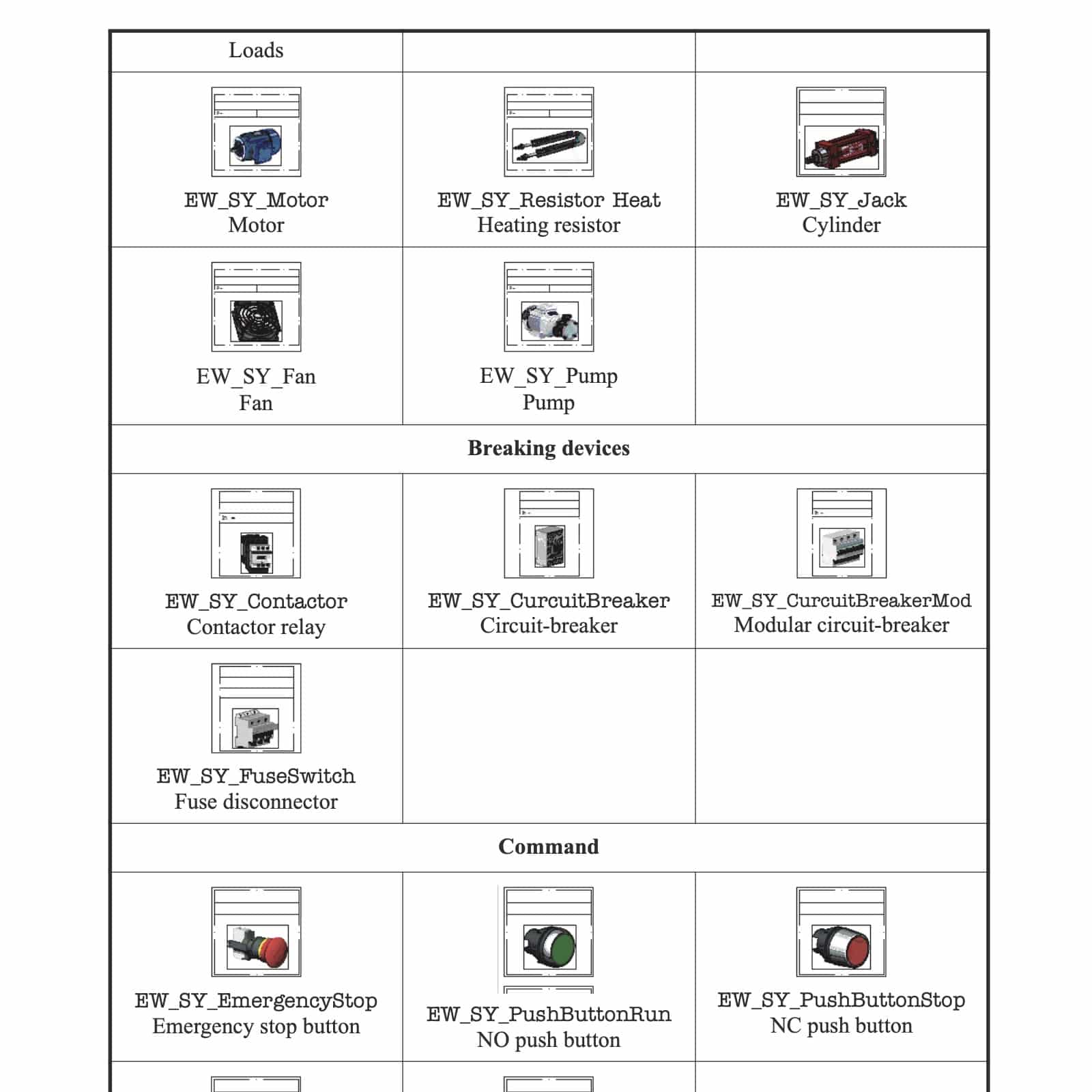
- Line Diagram Symbols
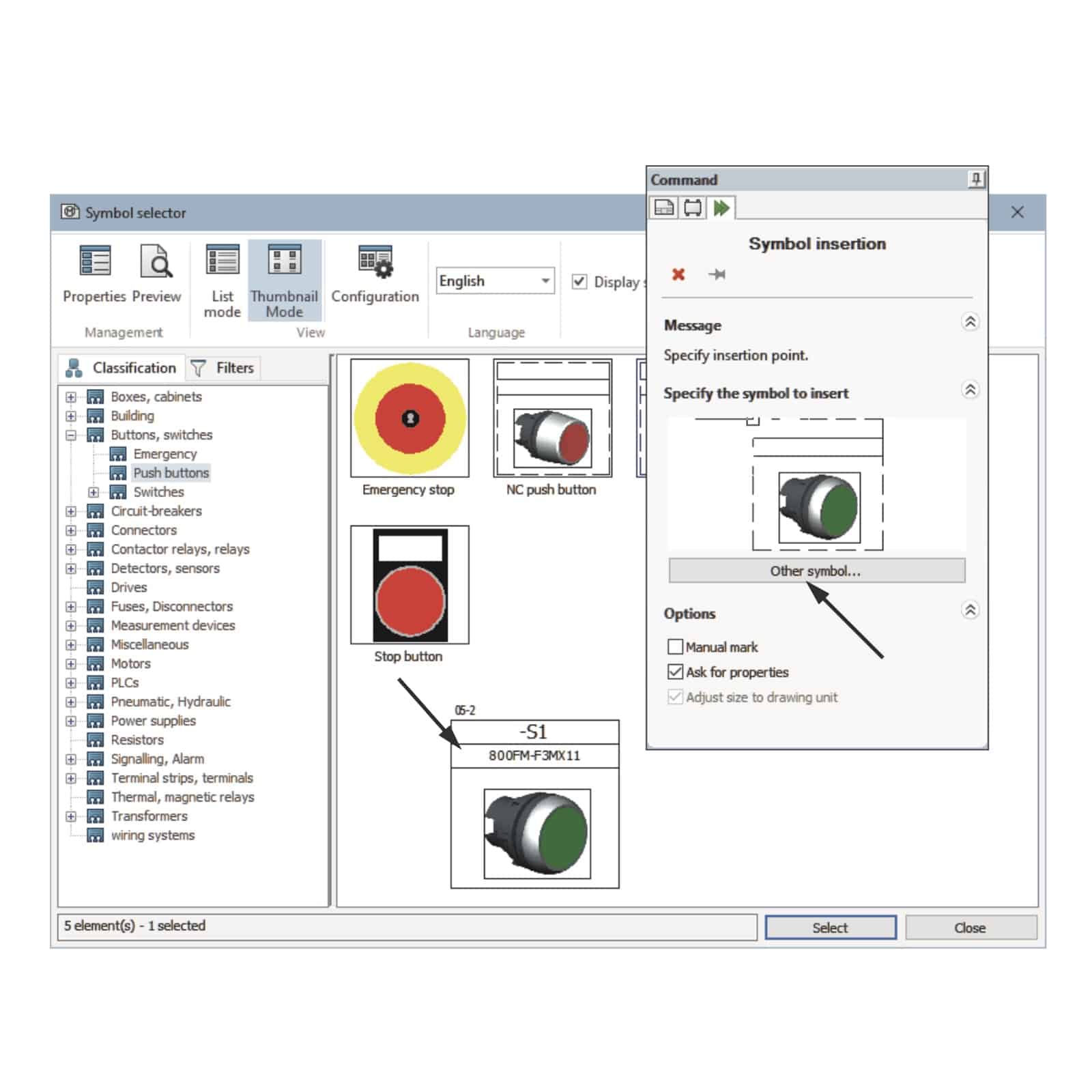
- Adding Symbols
- Symbols Library
- Symbol Orientation
- Adding Cables
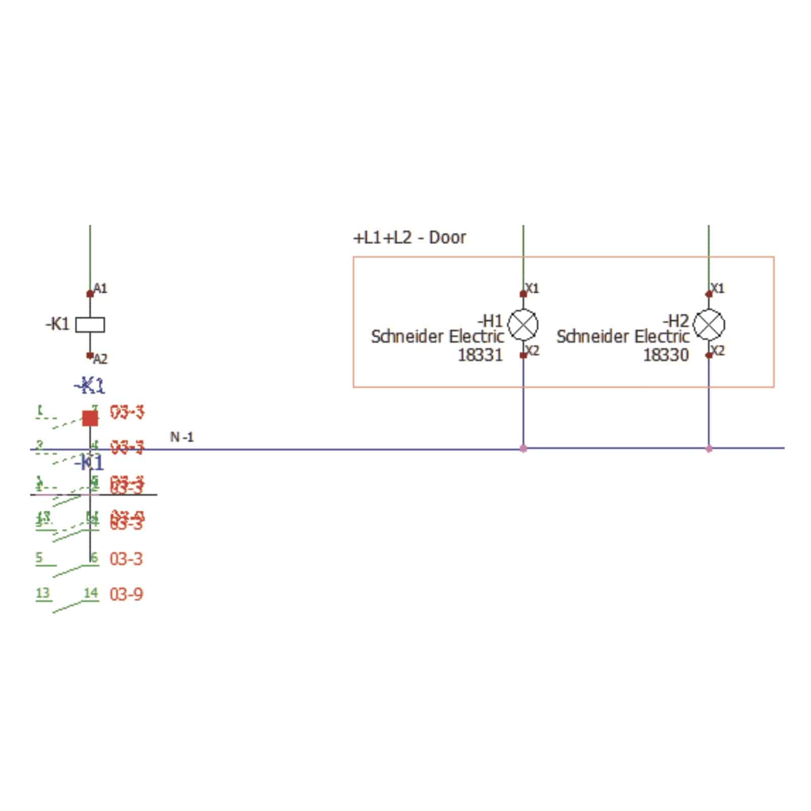
- Schematic Drawing
- Scheme Best Practices
- Symbols Panel
- Schematic Symbols
- Symbol Properties
- Types of Properties
- Exercise 3: Drawing Types
Lesson 4: Symbols and Components
- What is a component?
- Component Identification
- Component Symbol Identification
- Deleting Components
- Description Columns
- Symbol Component Association
- Exercise 4: Symbols and Components
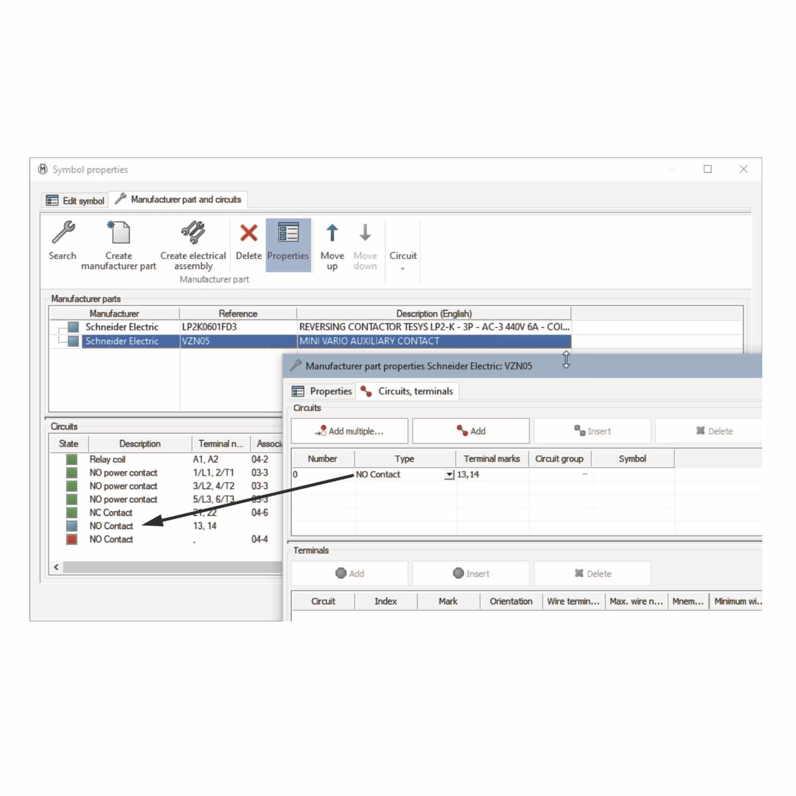
Lesson 5: Manufacturers Parts
- What are Manufacturers Parts?
- Circuits and Terminals
- Circuit Association
- Finding Manufacturer Parts
- Search Options
- Editing Parts
- Circuit Symbols
- Circuit Association
- Electrical Assemblies
- Exercise 5: Manufacturers Parts
Lesson 6: Wires and Equipotentials
- Equipotentials and Wires
- Wire Styles
- Wire Style Manager
- Numbering Group
- Replacing Wires
- Replacement Range
- Equipotential Numbering Results
- Wire Numbering Results
- Using Nodal Indicators
- Exercise 6: Wires and Equipotentials
Lesson 7: Cabling
- What is Cabling?
- Changes in the Wiring Diagram
- Cables
- Detailed Cabling
- Terminal Strip
- Pin to Pin Connections
- Wires
- Terminals
- Creating a New Cable
- Adding Terminals to the Strip
- Terminals Editor
- Copy and Paste
- Exercise 7: Cablin
Lesson 8: Symbol Creation
- Symbols and Standards
- Symbols Manager
- Symbol Properties
- Circuits, Terminals, Types
- Circuit Transmission
- Connection Point Insertion
- Multiple Attribute
- Splitting Attribute Data
- Add to Library
- Copy, Paste Symbol
- Exercise 8: Symbol Creation
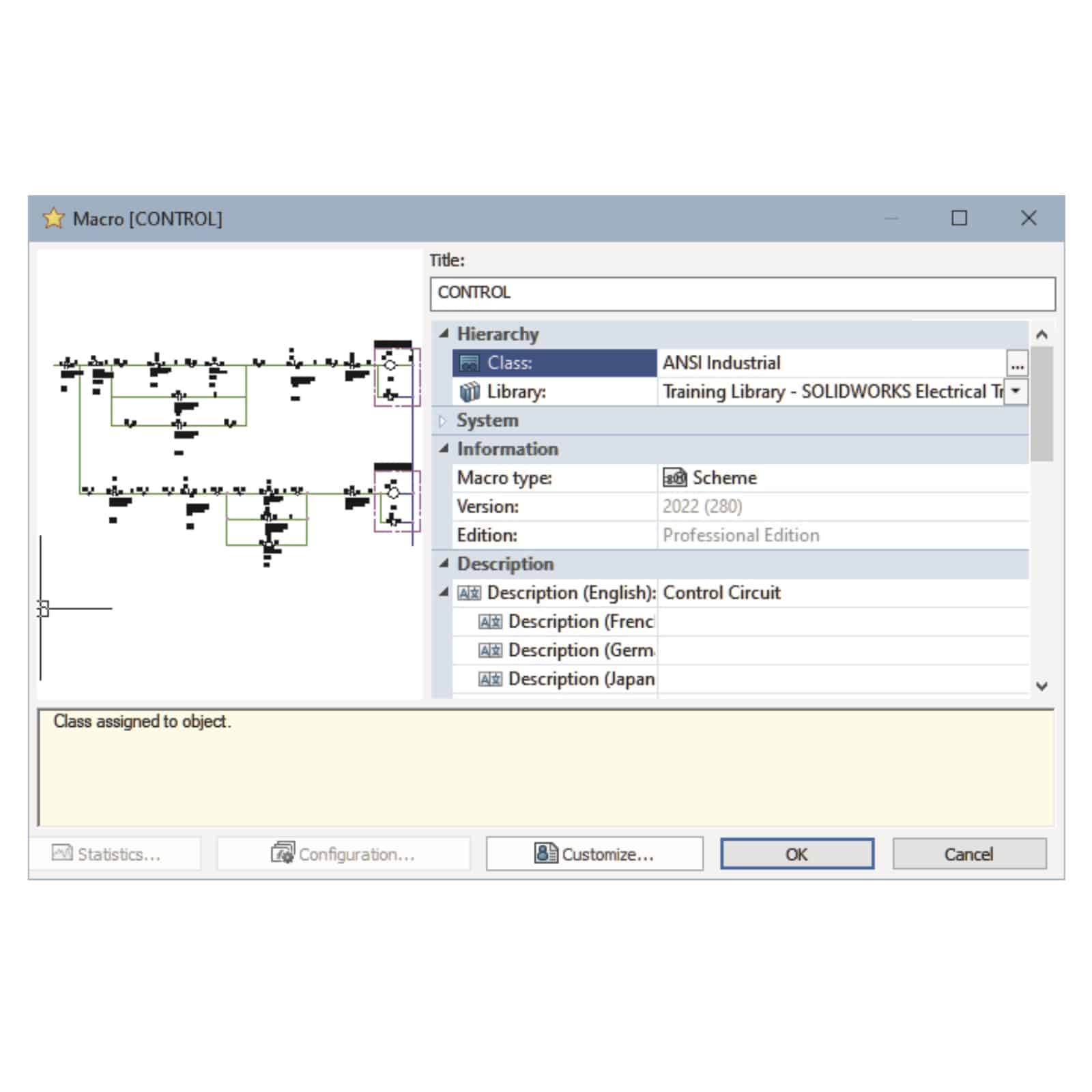
Lesson 9: Macros
- What are Macros?
- Creating and Adding Macros
- Creating a New Group
- Project Macros
- Paste Special
- Exercise 9: Macros
Lesson 10: Cross Referencing
- What is Cross Referencing?
- Cross Reference List
- Cross Reference State Colors
- Cross Reference Text Coding
- Cross Reference Types
- Same Level Cross Referencing
- Cross Reference Location Listing
- Exercise 10: Cross Referencing
Lesson 11: Managing Origin-Destination Arrows
- What are Origin-Destination Arrows?
- Origin-Destination Arrows
- Interpreting the Arrow Text
- Exercise 11: Origin-Destination Arrows
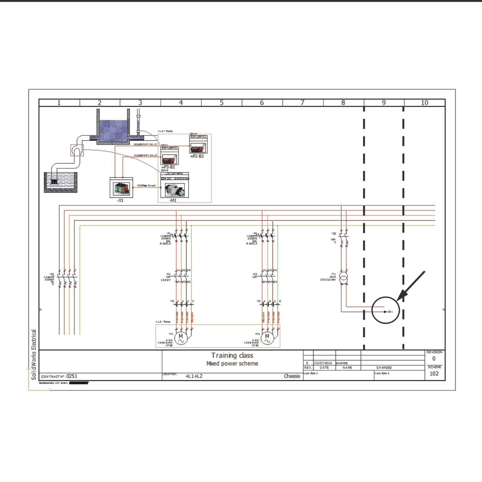
Lesson 12: Dynamic Programmable Logic Control
- What is a PLC?
- Dynamic Insertion
- Adding a New Scheme
- Adding a PLC Mark
- Inserting a PLC
- PLC Configuration
- PLC Configuration Options
- Editing Wires
- Editing a PLC
- Exercise 12: Adding a PLC
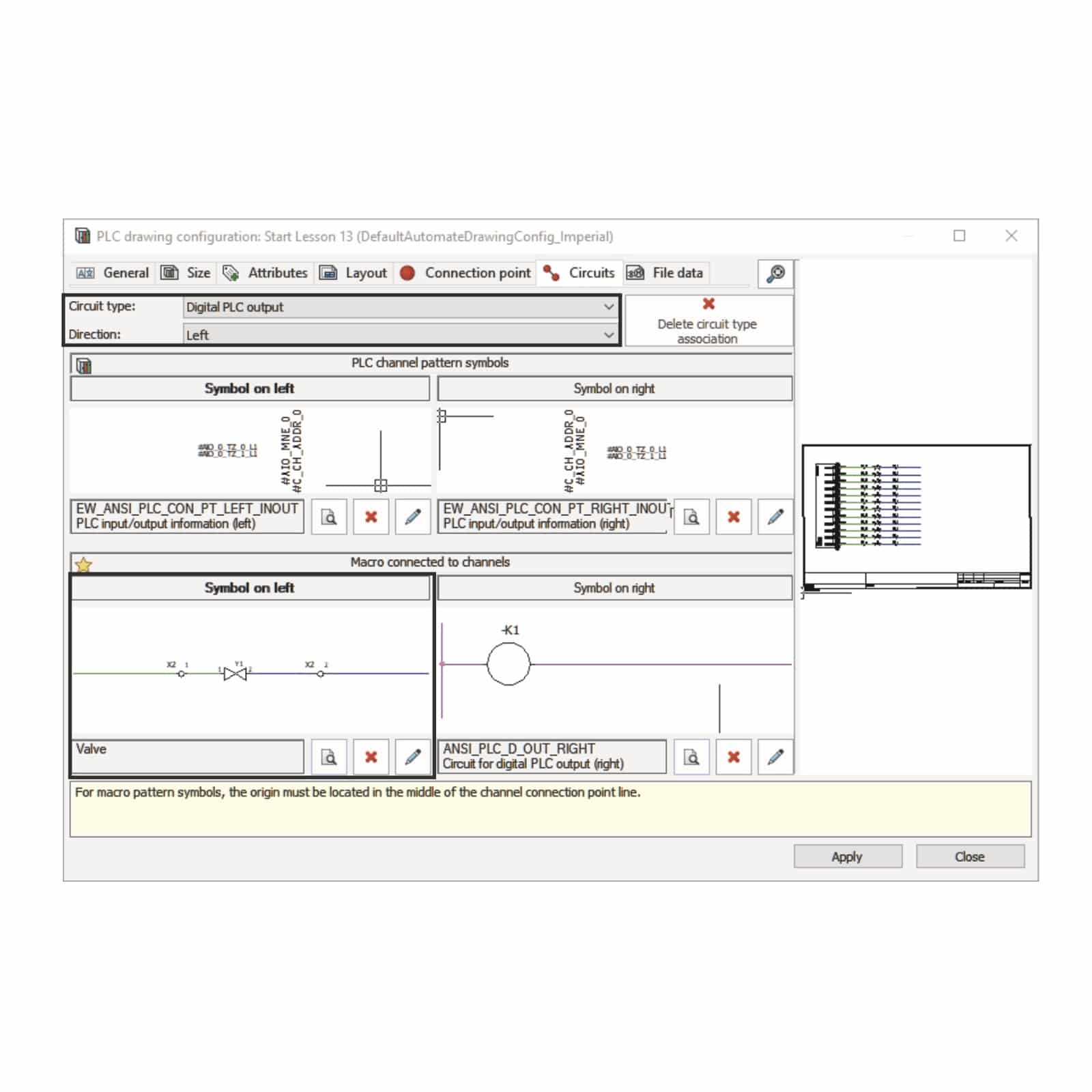
Lesson 13: Automated Programmable Logic Control
- How are PLCs Automated?
- PLC Mark, Part
- Manufacturer Data
- IO Manager
- Exercise 13: Automated Programmable Logic Control
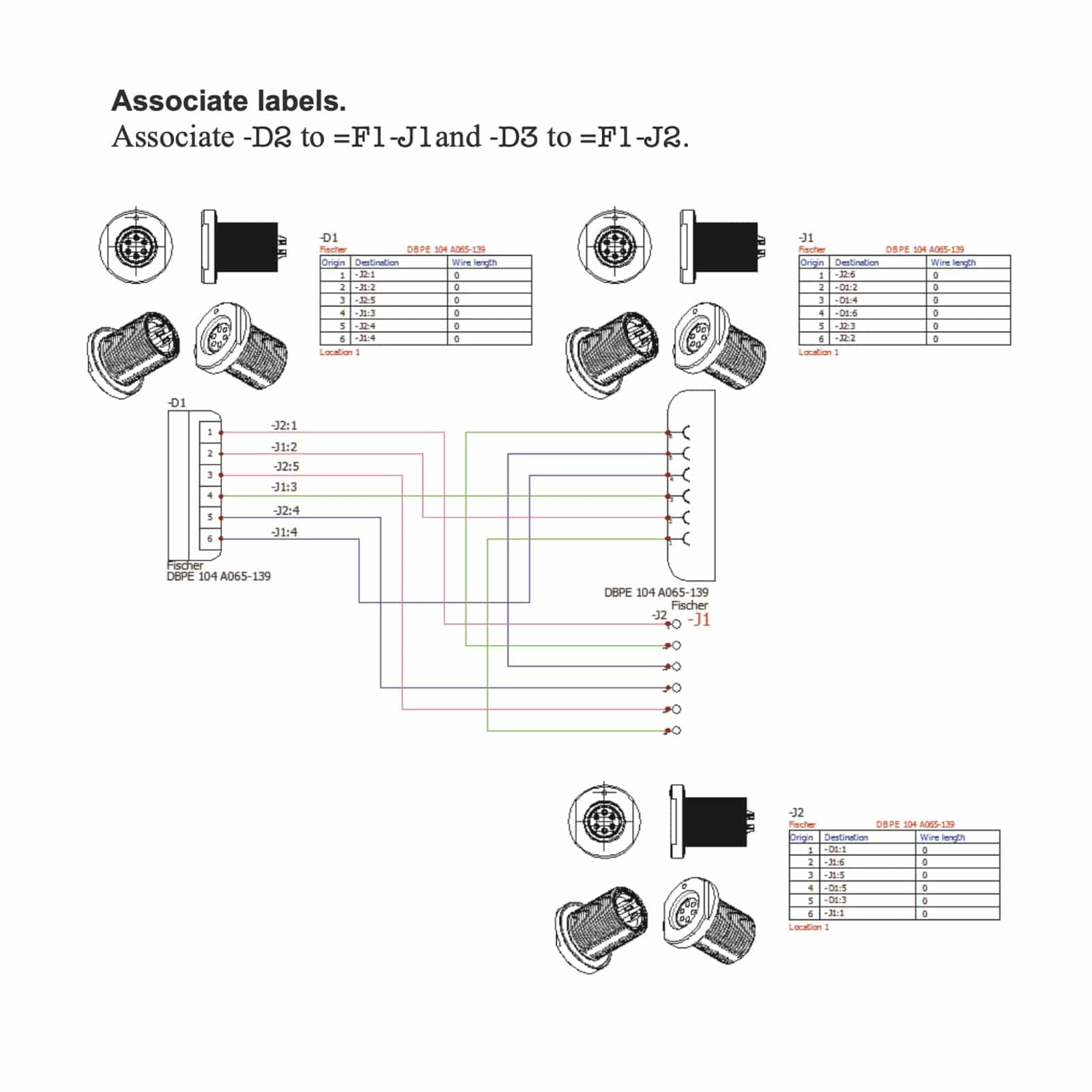
Lesson 14: Connectors
- Connectors
- Insert Connector
- Connector Insertion
- Exercise 14: Connectors
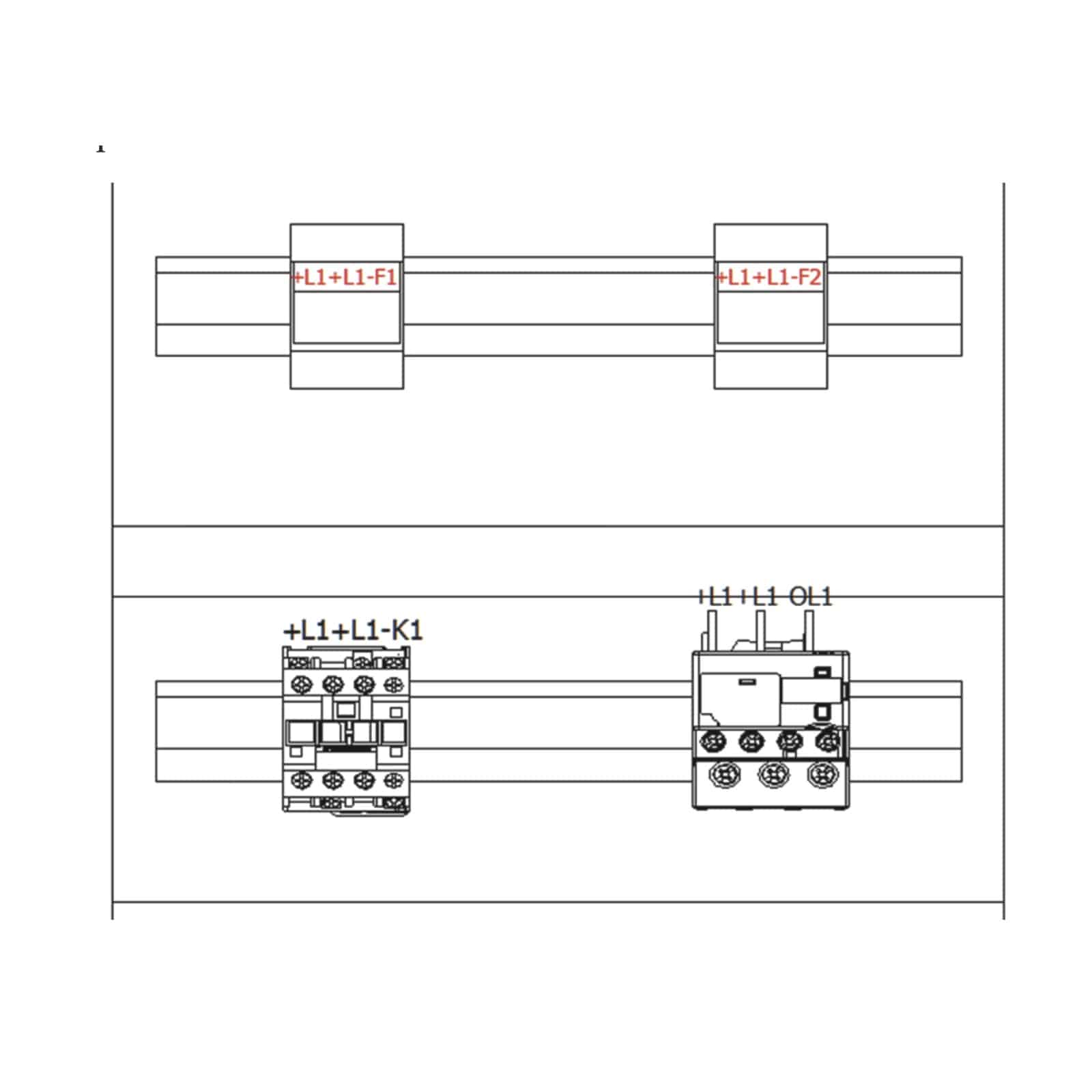
Lesson 15: 2D Cabinet Layouts
- What are 2D Cabinet Layouts?
- Creating a 2D Layout
- Inserting Ducts and Rails
- Inserting Components
- Wire Cabling Order
- Optimize Wire Cabling Order
- Exercise 15: 2D Cabinet Layouts
Lesson 16: Design Rule Checks
- What are Design Rule Checks?
- Unconnected Pins
- Equipotential Conflicts
- Max. Terminal Wires
- Duplicated Parent Symbols
- Child Symbols without Parent
- Empty Terminal Strip
- Duplicated Terminals
- Exercise 16: Design Rule Checks
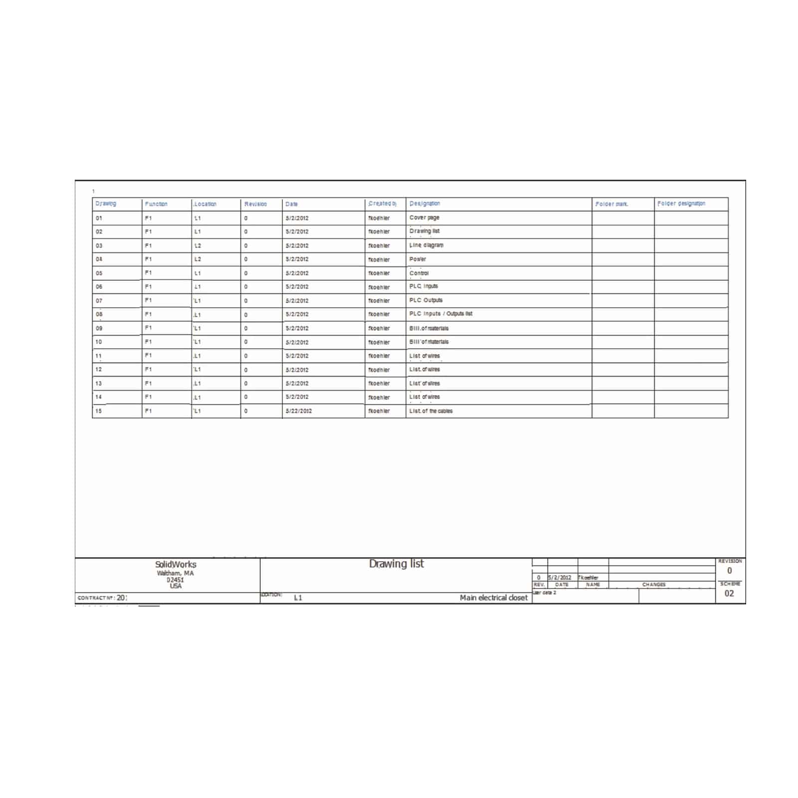
Lesson 17: Reports
- What are Reports?
- Bill Of Materials Grouped by Manufacturer
- List of Wires by Line Style
- List of Cables Grouped by Reference
- Drawings List
- Report Templates
- Report Columns
- Column Formula
- SQL Query Column Variable
- Sort and Break
- Schematic Report Tables
- Exercise 17: Reports
Lesson 18: Simple Reports
- What are Views?
- Stages in the Process
- Exercise 18: Simple Reports
